How to design a mask

PHOTOMASK PORTAL
  • WELCOME
    • What Our Customers Say
  • QUOTE
  • ORDER FORM
  • UPLOAD
  • DESIGN
  • DICING
  • LEARN
    • How to Design a Mask
    • How to Use LayoutEditor
    • MaskView Tips
    • Ordering Tips
    • Terminology
    • FAQ
  • STORE
  • Link Page
Picture
Careful preparation
for your design 
can result in 
an easy process 
and a great mask
for a low price.
Photomask Layout

Before You Start Drawing

  • Decide IF you want to draw the mask. If you do, we provide guidelines and best practices on this page to help you. If you don't, you can farm-out the design to us through our design service. Out talented team of engineers can put together just about anything based on your description.
  • Choose the software and design format you will use. GDS-II has been around for decades and is the industry standard and our preferred design format. OASIS is a newer format designed to replace GDS-II and is already the preferred format for high-end IC designs. OASIS has the benefit of producing much smaller files and works with true circles. OASIS and GDS-II both work great for laying out a mask. If you need a GDS-II / OASIS viewer with basic editing capability, LayoutEditor does this for free. If you need more advanced editing and automation capability, a commercial license for LayoutEditor can be purchased in our Store.
  • Know your Manufacturing Grid. Your design will be written with a Pattern Generator using either a raster-scan or a vector-scan technique. The raster-scan technique, commonly used by LASER-writers, requires a uniform grid size. Common grid sizes are 1nm, 5nm, 25nm, 50nm, and 250nm but there are many more possibilities.  Your mask will write faster with a larger manufacturing grid resulting in a lower cost. As the designer, you want to make sure that the features you draw are a multiple of the manufacturing grid to avoid grid snapping. 
  • Choose your Design Grid. Choose a design grid that is fundamental to the manufacturing grid. If your design grid doesn't match up to your manufacturing grid, your pattern will be snapped to the manufacturing grid. So plan your mask layout -- and your design grid specifically -- with your manufacturing grid in mind.  For the best results, set your design grid to be equal to the manufacturing grid before you start drawing and make sure that Snap-to-Grid is enabled.
  • Determine the size of the mask. The facility you are using will tell you what mask sizes the exposure tools can accept. You'll want to make sure the mask you buy has the correct thickness but the lateral dimensions (X&Y) are what we need to know for the design.
  • Determine the size of your drawing area. If possible, we request you to stay 7mm away from the edge of the mask. This gives us space to place our processing marks for reference, alignment, metrology, closure check, and SPC.  We'll also use this space to place several labels including your information (name, school, lab, project, mask) and ours (logo, time-stamp, serial number, and mask writer). But if you need your design to extend into this space, we can certainly accommodate you.
Photomask Extents
  • Consider scaling. Masks used for contact lithography or close proximity will be 1X, meaning what you draw on the mask will be the same size on the wafer. If you are designing a mask or a reticle for projection lithography in a 4X or 5X stepper or scanner, consider that what you want to produce on the wafer will need to be 4-5 times larger on the mask. Or tell us what you are doing and we can manage the scaling for you.
  • Decide if you will draw clear or dark features in the design. You should draw whichever tone is easiest for you to draw as these can easily be inverted later in the process with a boolean operation. However in some cases, like inverting a very dense array, it may be better to array the inverted shape and avoid a boolean operation. 
  • Plan your alignment system. For a mask aligner, cross-and-square systems are quite common for the alignment marks. Usually reference marks (shown below in yellow) are printed on the wafer with the first mask for complementary marks (shown in green, blue, red) to align to on subsequent layers. Credit to Cornell CNF for the original design. As shown in the graphic, color represents clear glass and black represents chrome.

Start Drawing Your Mask Design

Photomask Template Nikon Stepper
  • Start with templates. We can supply you with a template to help you get started. Just download our mask order form, complete the header section, and ask us for a template for your project in the comments section.
  • Keep centered. For simplicity, assign the origin of your coordinates to be the center of the mask.
  • Keep your perspective. If you will be using the masks for contact lithography, you'll probably want to draw your pattern the way it will appear on the front of the wafer. Even if you will be printing on both the front and the back of the wafer, draw all of your patterns for both sides of the wafer from this frame of reference.  At this stage of the process, you don't need to mirror any of the patterns in the design.
  • Keep square. As much as possible, draw features that are orthogonal and aligned with the primary axes. Instead of saying "axis-aligned orthogonal features", we call this "Manhattan geometry."
Manhattan Geometry on Photomask
Manhattan, New York City
The manufacturing grid on LASER-writers will be a uniform orthogonal grid, so it's best to stay on this grid as much as possible. Circular features will be "off grid" and drive you to a smaller manufacturing grid to minimize data-snapping. Moreover, the mask writer approximates your polygons using trapezoids. It can take a lot of really small trapezoids to approximate circular features causing your mask data (expressed as "trap count") to become large. As much as you can, stick with axis-aligned 90-degree or 45-degree angles.
Photomask Angularity
  • Minimize your vertices. If you need to draw circular features, try to minimize the number of vertices in the polygon used to approximate the circular shape. This will minimize the number of trapezoids the mask writer needs to generate to approximate the polygon. Shown in this example is a circle (the design intent) approximated by a 16-sided polygon in the design file which is fractured into seven trapezoids by the LASER-writer.
  • Keep structured. Use hierarchy in your design. This will make your job faster to draw, easier to revise, and with less chance for error. You'll also produce a much smaller file at the end. Please do not flatten the hierarchy before sending it to us. Just keep the hierarchy and tell us the name of the cell in your hierarchy we should use to produce the masks.
  • Check your CD. The CD, or critical dimension, is where we will measure the dimension of a feature on the mask and make sure it is within the tolerance specification. At this point, just make sure that the feature you will designate as your CD is a multiple of the manufacturing grid you intend to use.

When You Are Finished Drawing

  • Complete the mask order form. The mask order form is how you 
  1. map the layer(s) in the design file to physical masks, 
  2. designate the mask tone, 
  3. designate the mask parity, and 
  4. designate the CD.
Photomask Order Form
  • Map the layers in the design file to the physical masks. It might be as simple as layer 1 in your design file represents mask 1 and layer 2 represents mask 2.  But sometimes you need to make a logical combination of multiple layers in the design file.  You can do this with boolean operations on polygons.  Our simple order form allows for a boolean operation between two layers but more complicated boolean combinations are possible. If you need added capability, just ask.
Boolean Operations on Polygons
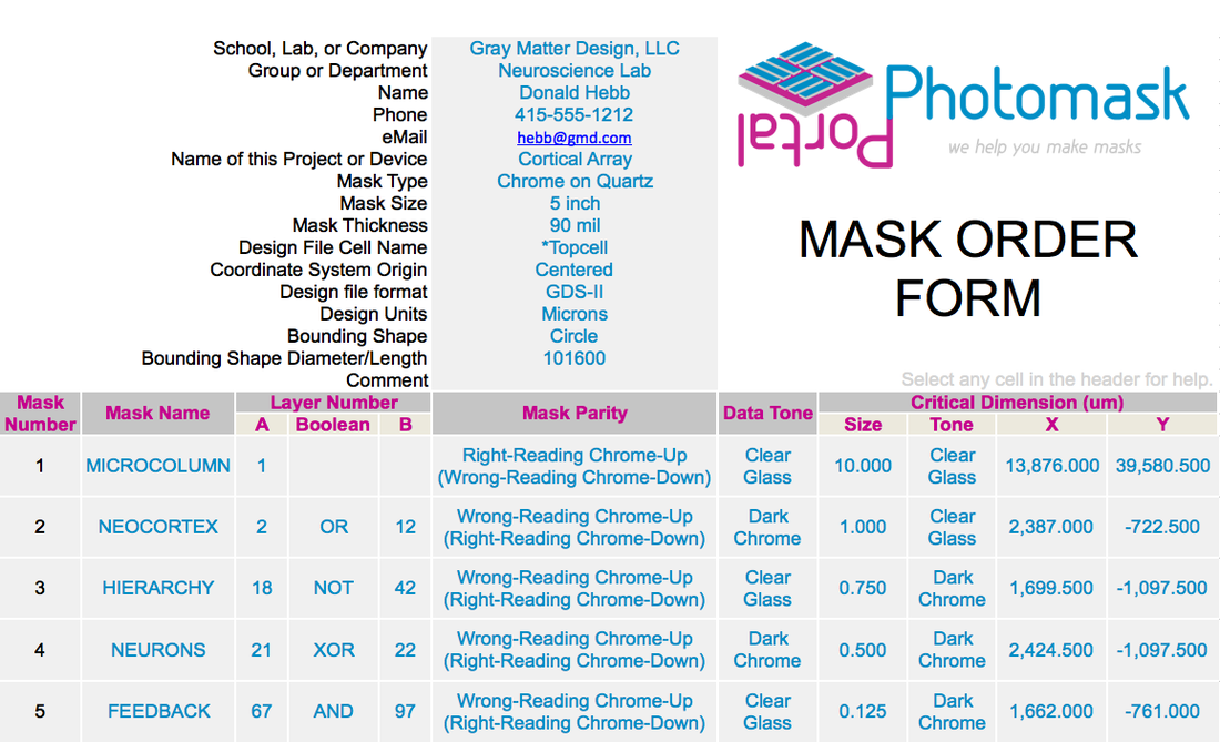
  • Designate the mask tone. Mask tone is not mentioned anywhere in the design file. In fact, when you are drawing polygons in the design file, you are actually drawing the interface between tones. The EDA software will color the body of the polygons but that is simply to indicate that the polygon is closed and has nothing to do with mask tone. Mask tone must be specified via documentation such as the mask order form where you specify if the the body of the polygons in your design file (also known as your digitized data) should be clear or dark on the mask. This is not the same as specifying "field tone", terminology we try to avoid since it can be ambiguous.
So now we know:
  1. Tone is specified as the body of the polygons (shown in blue on the following diagram).
  2. LASER-writers always expose the polygons.
  3. Positive resist is commonly used on chrome masks. 
Together this means that polygons you draw in your design file will result in clear glass on a chrome mask. This is great if you specify the data tone as clear, but what if you specify the data tone as dark? 
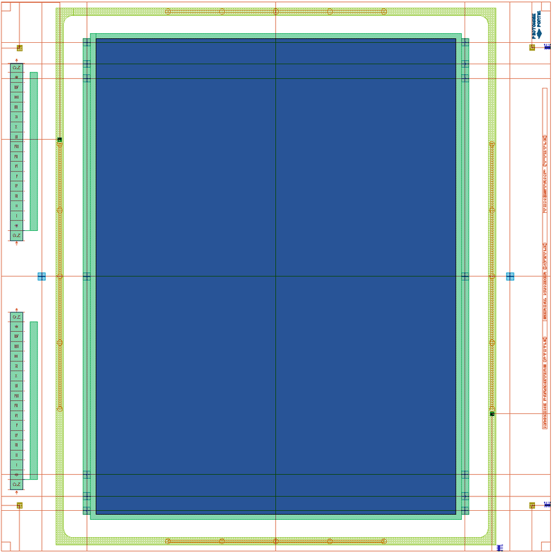
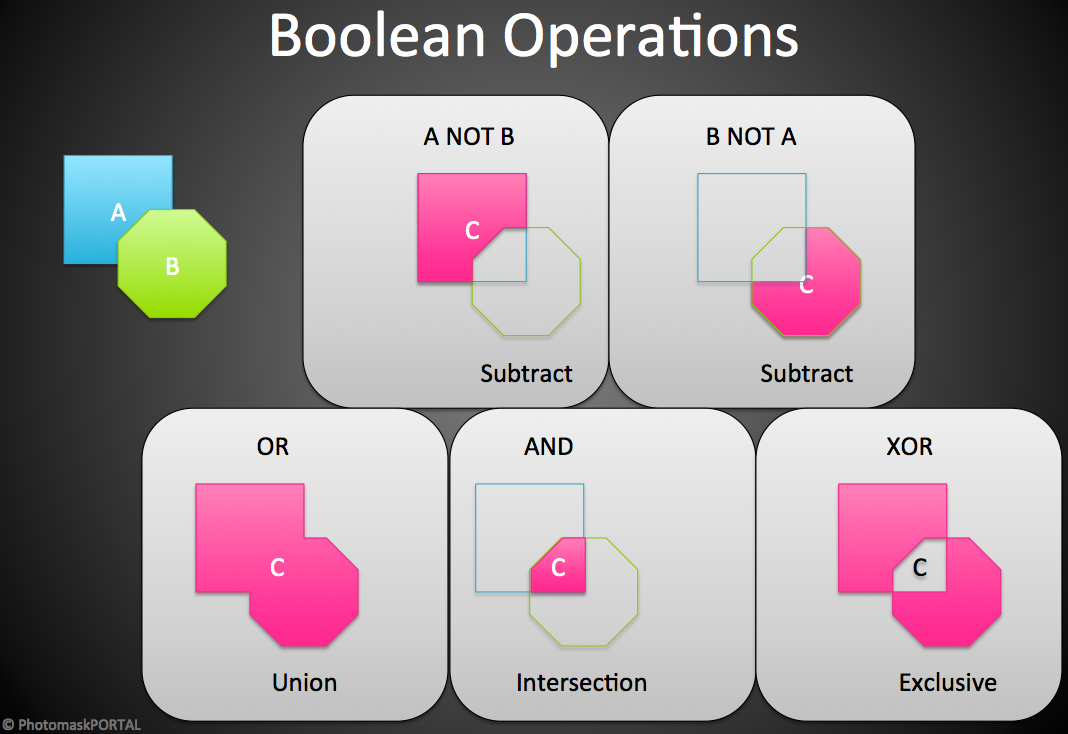
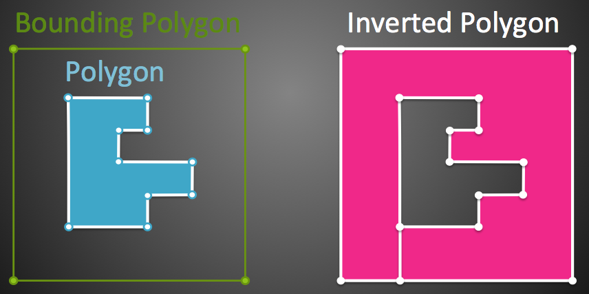
In this case, we will invert your polygons (shown in blue) with a bounding polygon (shown in green) to create an inverted polygon (shown in red). 
Inverting a Polygon on a Photomask
Now when the LASER-writer exposes the inverted polygon on positive resist, the area around the feature will be clear glass and the feature will be dark. This bounding polygon can be any shape (like a circular wafer with an alignment flat) but is commonly a rectangle (also referred to as "window"). Note: Emulsion masks (like film masks) behave the opposite way since emulsion acts like a negative resist.  With emulsion masks, polygons in your data translate to dark features on the mask.
  • Designate the mask parity. Mask parity can be a confusing concept the first time you build a mask.  If the pattern you design is not "mirror symmetric", it will appear as a normal image from one side of the mask and a mirror-image from the opposite side.  
Photomask Parity
To clarify, we borrow terminology from photography called Right-Reading and Wrong-Reading. In photography, the original image is defined as Right-Reading and the mirror of the original image is called Wrong-Reading.
Image Parity and the Photomask
In photolithography, we define the original design pattern you supply (whatever that may be) as Right-Reading and the mirror image of the design pattern as Wrong-Reading. Typically the original design will have normal text resulting in a wrong-reading image with mirrored text but that doesn't have to be the case.
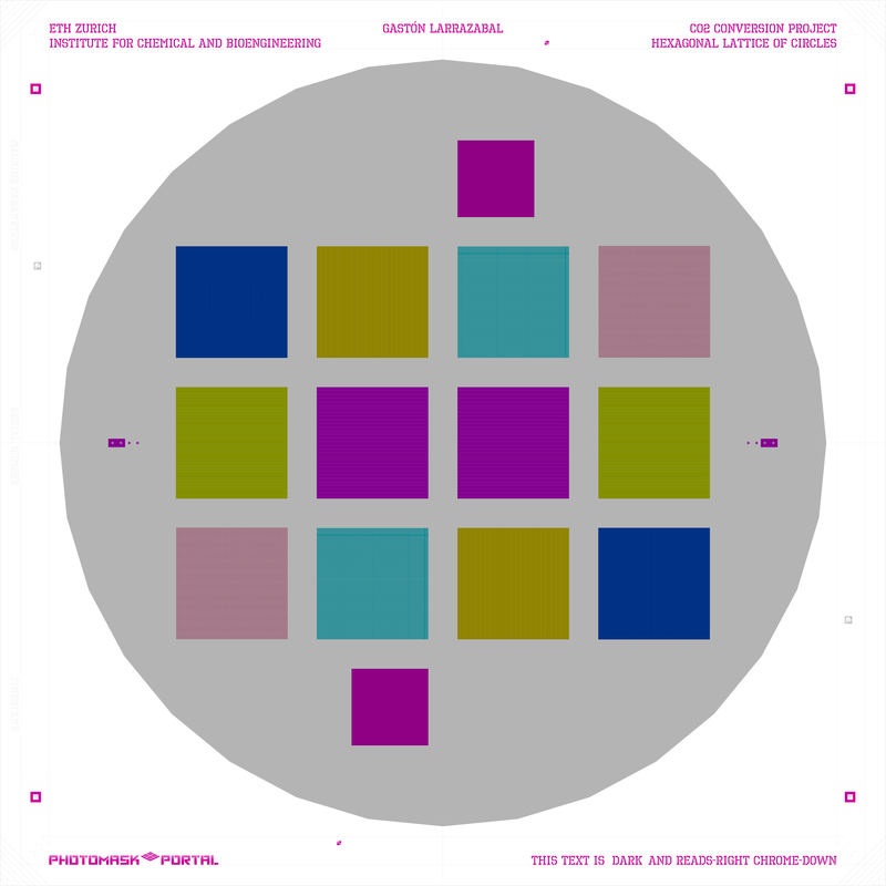
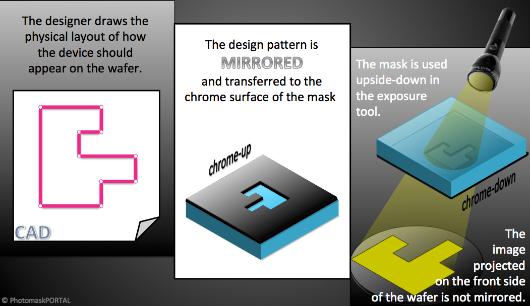
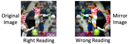
To specify mask parity you must state both the image parity (right-reading or wrong-reading) and the frame of reference (chrome-up or chrome-down).
Photomask Parity Right- and Wrong-Reading
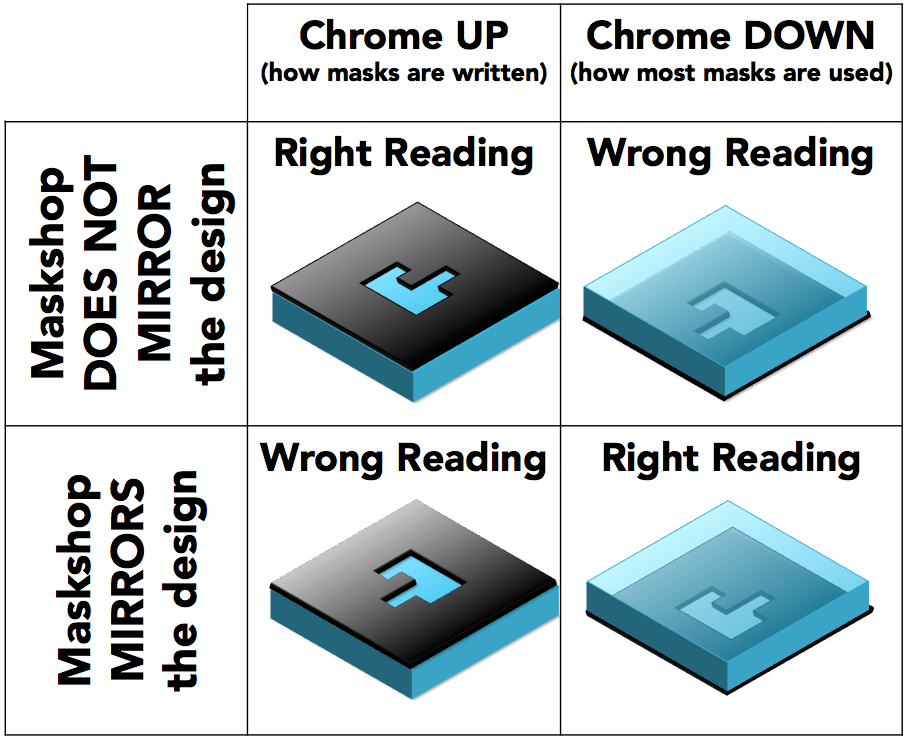
Specifying Wrong-Reading Chrome-Up (or the equivalent Right-Reading Chrome-Down) will cause us to mirror your pattern.
Note that there are only two possible mask combinations since Right-Reading Chrome-Up is the same physical mask as Wrong-Reading Chrome-Down and Wrong-Reading Chrome-Up is the same physical mask as Right-Reading Chrome-Down. The important thing to note is that if you specify Wrong-Reading Chrome-Up (or Right-Reading Chrome-Down) on the mask order form, we will mirror the design you supply before writing it on the mask.
  • Designate the CD. The CD is an essential part of ordering a mask. The CD you designate tells us there should be a certain feature type {line or contact} of a certain tone {clear or dark} that measures a certain distance across at a certain coordinate on the mask. If we don't find the feature you described at the coordinate you specified, we know something is wrong with the set-up. Also, since we will measure the CD to make sure it is within the specified tolerance, we will optimize our process to produce this feature type as accurately as possible.  So the CD should be the feature type you would like produced with the greatest accuracy and precision.  This may or may not be the same as the minimum feature size on the mask.  If you are deriving your mask pattern from a boolean combination of other patterns, it is a good idea to choose a CD that will only exist and be the correct tone if the boolean is done correctly.
  • Compress your design file. ZIP, GZIP, and RAR are common techniques. You should keep your hierarchy and, if possible, strip away any cells that are not needed to build your masks.

Upload Your Design File

  • After the design is finalized and the mask order form is completed, proceed with Step 2 of our 3-step process.

About Us

How We Make Our Masks
​
Contact Us

Legal

Privacy & Warranty 
​Terms of Sale

Support

FAQ
Terminology

© 2021 PhotomaskPortal
All rights reserved
  • WELCOME
    • What Our Customers Say
  • QUOTE
  • ORDER FORM
  • UPLOAD
  • DESIGN
  • DICING
  • LEARN
    • How to Design a Mask
    • How to Use LayoutEditor
    • MaskView Tips
    • Ordering Tips
    • Terminology
    • FAQ
  • STORE
  • Link Page